VARMS Stardust Half A Build
Admin: Andy Smith Cover Pictures: Alan Jenkins Contributions: Alan/Gary/Tim/Kevin


Background to the VARMS Half A Stardust
Our Local VARMS Half A Rules:
These rules create an exciting and friendly competition environment.
Eligibility:
- Any Half A design can compete.
- One-design VARMS Stardust models are also allowed to participate, with separate winners in each division.
Competition Structure:
- Simultaneous Launch: All competitors launch their models at the same time.
- Endurance-Based Winner: The last model to land is declared the winner.
- Landings: Only landings on a nominated part of the airfield will be counted, you are disqualified if you outland this nominated area.
- Timer: Designated person on the day to record participants flight times. Ongoing log to be kept.
Timed Events (if time is a constraint):
- A specific duration, such as 20 minutes, can be nominated
- Only models that are still airborne at the end of the nominated duration time (e.g., 20 minutes) are eligible to be counted for determining the winner.
- The model with the most remaining battery capacity at the end of the time limit is the winner. To further ensure a level playing field, the same battery checker will be used for all aircraft.
Divisions:
- Winners can be determined in both the Half A and VARMS one-design Stardust divisions to account for different model types.
5. One-design Stardust Rules:
- Electronic Speed Controller: To ensure the safe return of the model, the ESC must be programmed to maintain radio control functionality even after the motor has stopped due to a low battery.
- Battery: The maximum battery size is a 2s Lipo at 460Mah. Moreover only the VARMS sanctioned batteries are to be used.
- Propellers: Pilot's choice (Typical 6x4 to 8x3.8)
- Motors: Sunnysky x2204 KV1480 Brushless
- Flying Weight: Minimum flying weight 300 grams/ 10.5 Oz
- Airframe and Hardware Integrity:
To ensure uniformity and fairness, no modifications to the airframe or hardware of the one-design kit are permitted unless explicitly approved - Any proposed changes or modifications to the kit must be submitted to the Stardust Committee for review and approval. Only after receiving approval will the modifications be considered eligible for competition.
- Competitors must adhere strictly to the approved design specifications. Failure to comply with the approved one-design kit will result in ineligibility to compete in the one-design class.
These rules ensure that both strategy and skill play crucial roles in determining the winner, making the competition engaging and a learning experience for all participants.
Approved Variations
- None at this point
Any known issues and version control:
- Based on feedback, the V2 of the 3mm fuselage build board has been refined with more precise tolerances for the formers. Additionally, the fuselage side stringers have been adjusted for a closer fit.
- The servo orientation in tandem one behind each makes maintaining servos difficult as it difficult as the servo screws are shielded by the frame. Suggestion is to rotate the servos 90 deg so the servo screws can be accessed from the side. Status Under consideration.
- The original Stardust has a rear downward face keel. The one design seems to fly very well without the keel, however if you what to try a rear keel then is would be not be bretch of the rules.
The Stardust Fuselage and Tail Laser Parts

STARDUST
Fuselage Building Instructions
Preparation
* Sharp Blades
* Set Square
* 2 Mini servos 1.6kg MG90s/HXT900/EMAX ES08A
Building the Stardust Fuselage.
Attach the fuselage base jig to a flat board.
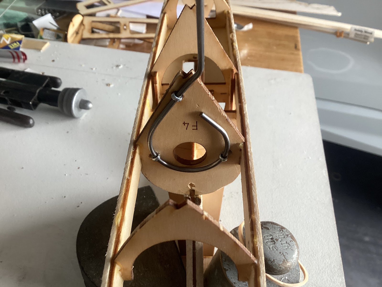
Attach F4A to the rear side of F4. Drill holes through
and trial fit the undercarriage with split pins.

Clear out with a drill the 1.5 mm holes for the pushrods in F7,8
and 9.
Check fit of servos in the tray. Modify if necessary.
Glue supports on the underneath to take the servo screws. This picture does not show the middle support.....

Select F5. Carefully cut/score the outer ply layer on the
rear side, where there are 2 small horizontal slots. Then bend/crack the former
at this location, to allow the top part to bend forward. Glue the 2 # 5 braces
to the front side to set the angle. Repeat the same process with F6, but do not
glue the braces for now.


Assembly
Glue F1 to the jig using the down thrust jig to set
the angle.
Glue F4,5,7 and 10 in place. Making sure they are seated flush with build board.
The down thrust jig also has a 90-degree angle to help locate the formers upright when glueing. CA is a good choice using kicker to set.
Locate remaining formers F8,F9,F11 in place without
gluing.
Assemble the pylon piece to F4,5,6 and 7. Glue in
place.

Fit the 1.5mm ply side rails to the formers.
Locate F4B and the servo tray in place before gluing the side rails to the formers. It also makes sense to fit the servos now before gluing the servo tray in place.

Add 2/#6braces
to the rear side of F6. Adjust the angle if needed. Apply thin CA to the crack
lines in F5 and 6 for reinforcement. Note the braces should make contact with the side rails.

Fit boom top stringer to F10, then mark and cut the
front end to match the pylon ply angle. Glue in place.

Cut all formers to remove the fuselage from the jig. Trim the lower portions of the formers.
Now add the lower hardwood 4x4 mm stringer.
While there is easy access, fit the undercarriage to
the front side of F4. Adjust the bends to place the axle in a central position.


-
Fit the three Pins and Undercarriage Wire through the front
of F4 & F4a, and align so that the extension of the wire carries up past
the Right Hand Side of the Fuz

Fit the provided washers over the back of the Split Pins, Cut to shorten the Pins, then fold the Pin arms back over the washers as tightly as possible
-
Consider whether you are happy with the shape and location of
the resultant undercarriage, and bend as required to suit your preference.
Add 1.5 balsa caps to the side rails from F1 to F7. Bevel this from F6 to zero at F7.
Sheet with 1.5 balsa,from the side rails lower edge
to the lower stringer, from F1 to F4. See photo.Finally, balsa sheet the curved
part of F4 and F4B. Extend it from F5 to 20 mm forward of F4. The canopy will
rest here.
Attach F1A to the front of F1. Best practice here is make F1a the same shape as F1. This allows a better glue surface for 1.5 mm planking.

Add the other balsa pieces to the pylon then shape.


- Lay Baseboard flat on Ridged Base. Set up Former 4 vertically to rear rebate and glue in place. Similarly take formers 3 and 2 placed vertically into rebate and glue so that each former has a nominal 1.5 mm gap to base edge.

.JPG)

- When Dry, place baseboard and glued formers onto fuselage, so that Former 4, sits adjacent Fuz Former 4, this leaves a nominal 10 mm gap between the front of the baseboard and Fuz former 1. Take a 3 mm drill and Drill through Former 4 and F4 of Fuz, to enable and align a nominally 8 mm long length of Dowell
- Fit Cowl Former 1A into the gap that exists between Former 1 and Baseboard, noting that the bottom tang fits down between the crutch’s at an angle.


- Take Build Jig with Pins set in, and glue and build up strips onto base, with Rubber Bands holding down Strips while they dry.
- Build up Strips until complete Cowl is filled in. With Luck, you will end up with having to create a double tapered infill piece nominally 6mm x 3 mm which is then glued into place to seal up the stripping.
- Sand Fair and finish as required. ( It can be painted, Stained, or covered with matching or contrasting covering. !! Your Call )

The pylon 1.5mm ply cap is added after covering.
Push rods. A 1.0 mm. wire will do for the push rods.
They exit the fuselage at the top of F10, either side of the balsa stringer.
Canopy. This can be made from a drink bottle from ALDI. Alternatively, Gary has done the files for a built-up ply/balsa unit which looks very cool!
To provide a gluing area for the attachment of the
elevator, add a piece of 3.0mm. balsa into the triangular space behind F10,
flush with the top of the side rails.
ELEVATOR AND RUDDER
A 10 mm piece needs to be removed from the inboard end of each elevator pieces to clear the fuselage.
A 20 mm wide piece of balsa is added to the top
of the fuselage. The left and right parts can be joined by a wire torque rod.
See Kevin’s model.

Gary has sent some covering techniques.
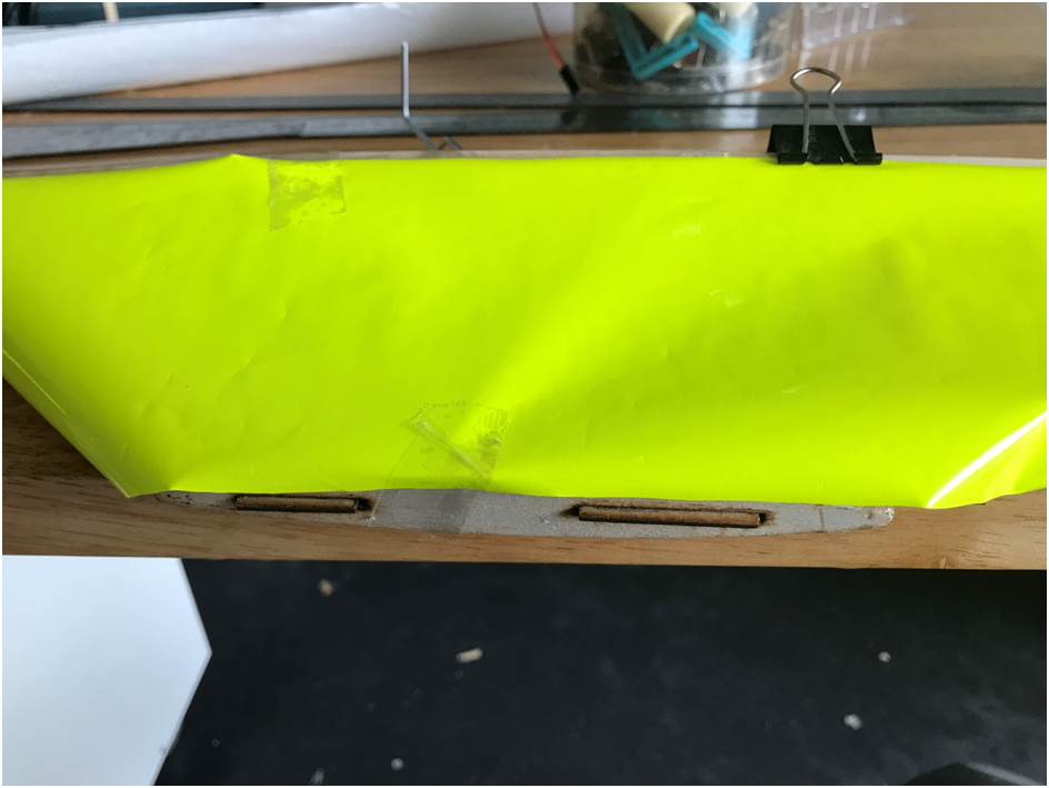
- - Pull over Covering on flat sections and use Heat Iron to fold over a Nominal 5mm Seam.
-
Around Curved Pylon area, Cut 15 to 20 mm wide tabs, by
carefully cutting down towards Pylon sufficiently to enable you to pull over
sections of covering until you can pull over and with heat iron, heat down
covering onto back of Pylon area.
Continue this same method the both front and back curved areas of the
Pylon.

Finish of with Heat Iron until you are satisfied with your seams.
You don’t have to finish shrink the remainder or this side yet, can
clean up seam and commence to repeat the second side.


STARDUST WING
BUILDING INSTRUCTIONS.7/24
Preparation
1)
Glue together the following ribs.
A2, A1, A1,A2A14,B1,B2B2,B1,A14
2)TE. Orientate left and right
components. Bevel the top aft section of the TE, down to 1.5mm.
3) Assemble and glue the tips
as shown in attached plan. Thin CA works well. Note the distance front to back
should be 130 mm. as shown. Bevel top TE portion to 1.5 mm and round the LE
section.
4) Assembly. Borrow a wing
building jig from VARMS.
Assemble the centre section of
the spar.NOTE. Using Titebond will produce a thicker spar than thick CA (
Gorilla Super glue. Bunnings)Also variation in thickness of the ply and balsa
produces a thicker spar. This means the rib slots may need to be widened to sit
on the spar.See attached diag.Orientate 5mm balsa components.To build, start
with joiner 1. Mark centre line. Glue in place one balsa A, followed by the
other butting in the middle.At this point, dry assemble joiners 2 and 3 and
check the fit of some ribs. If necessary, the balsa can be sanded a little to
allow easier fitting of the ribs. Glue joiner 2 centred onto balsa.Turn the
spar over and glue joiner 3 to the centre of joiner 1. Complete the outer spar
on the wing jig. This makes it easier to match the angle.
Note that when the spar is
installed Joiner 3 is on the rear side.
Add 20 mm. wide sticky tape to the surface of the jig
at the spar/rib and TE/rib junction. This prevents gluing parts to the jig.
1)
Spar.Temporarily place the spar centre
section onto the build jig near the TE locating the centre. Clamp in place.Locate
and glue balsa B to A using the jig to give the correct angle. Then add the
joiners 4.Remove from jig.
2)
TE. Check the end slots of the TE
pieces match the widths of the matching laminated ribs. Locate and clamp the TE
pieces flush with the jig edge.
3)
Sit the spar in place with the laminated
ribs located in their TE notches. All ribs must sit onto the build jig.The rib
slot may need adjustment to fit. Add clamps to hold these in place. Glue with
thin CA.
4)
Locate and glue the remaining full
ribs. With each rib make sure it sits fully int the TE notch and is sitting onto
the jig.
5)
Add the 5mm round LE pieces. Note
outer panel LE extends 22 mm. beyond B8.
6)
Add and glue the sub ribs.
7)
Install the tips and remaining ribs
B9 and B10. Add a piece of scrap balsa behind the 22 mm. LE outboard of B8.
This allows for shaping of the underside of the LE area at B8 to match the aerofoil.
8)
Add 6 triangular gussets to the A1, A14,B2
junction with the TE. Add a small piece of thin ply (not provided)over the top
of A1,2 TE junction for protection from the rubber bands.
9)
Sand and cover.
Note there is no need for washout to
be applied.
Some pictures from Colin Karn's build


Comments
Post a Comment