
Building the AREA17 Bird of Time Kit

 AREA17 Bird of Time Kit 


About this BOT:

This laser cut version of the Bird of Time was developed by AREA17

Although the wing planform closely adheres to the original Bird of Time design, slight adjustments have been made to facilitate the introduction of a brushless motor and battery. Notably, the fuselage has been extended by approximately 4 inches.

Where possible we have made the kit click to together. It can be built without a paper plan.

The all up weight of this kit with a brushless and battery ready to fly is typically lighter than the original non motor build. The original had a wing loading of 10 oz sqft this version was only 6.5 oz sqft.

Wingspan: 118″ (3000mm)

Length: 53″ (1340mm)

Wing Area: 1090 sq in 70.3 sq dm) 

Flying weight: 1.4 kg

COG: 100mm from leading edge


Wing Loading: 6.5oz/sq ft (19.7g/sq dm)

The laser kit includes:

  • Fuselage Formers
  • Fuselage 4 mm Balsa Sides, Bottom and Top
  • Fuselage 3 mm servo tray
  • Balsa and ply wing ribs
  • 3mm Ply Wing Spars
  • Leading Edge Stock
  • 2mm Shear Webs
  • 6mm Balsa Quad
  • 25mm Trailing Edge stock (needs tobe hand shaped)
  • Rudder
  • Tailplane
Fuselage and Tail parts supplied.


Wing Parts Supplied.


What you need to complete:

  • 2 x Mini Servos about 2.0kg or larger Eg. Corona DS929HV
  • Motor Dualsky XM2838EG-11L Brushless Motor about 300watts
  • Folding prop 11x7E or 11x8E
  • 35-45 amp ESC with BEC
  • 1500-1800Mah  3s Lipo
  • 1.6mm piano wire for push/pull servo control
  • Servo Clevis
  • 4ch RX
  • 1.5mm Balsa wing sheeting, false leading edge
  • Iron-on covering

 Tools:

  • Titebond Original and CA
  • Box Cutter
  • Pins


Getting started:

Building the Fuselage:

As a general note; when gluing the BOT together we use Titebond Original and CA in combination. If you dab some Titebond on the surface and then add a few drops of CA and press together no clamps are required.

Optional: We put some coloured food dye behind the lettering.


Glue the multi part formers together. (F1,F2,F3,F4)

*Note F1 is two layers of 3mm ply, F2,3,4 are laminated 3mm ply/4mm Balsa/ 3mm ply while F5 is just 4mm balsa.

Next the fuselage sides;
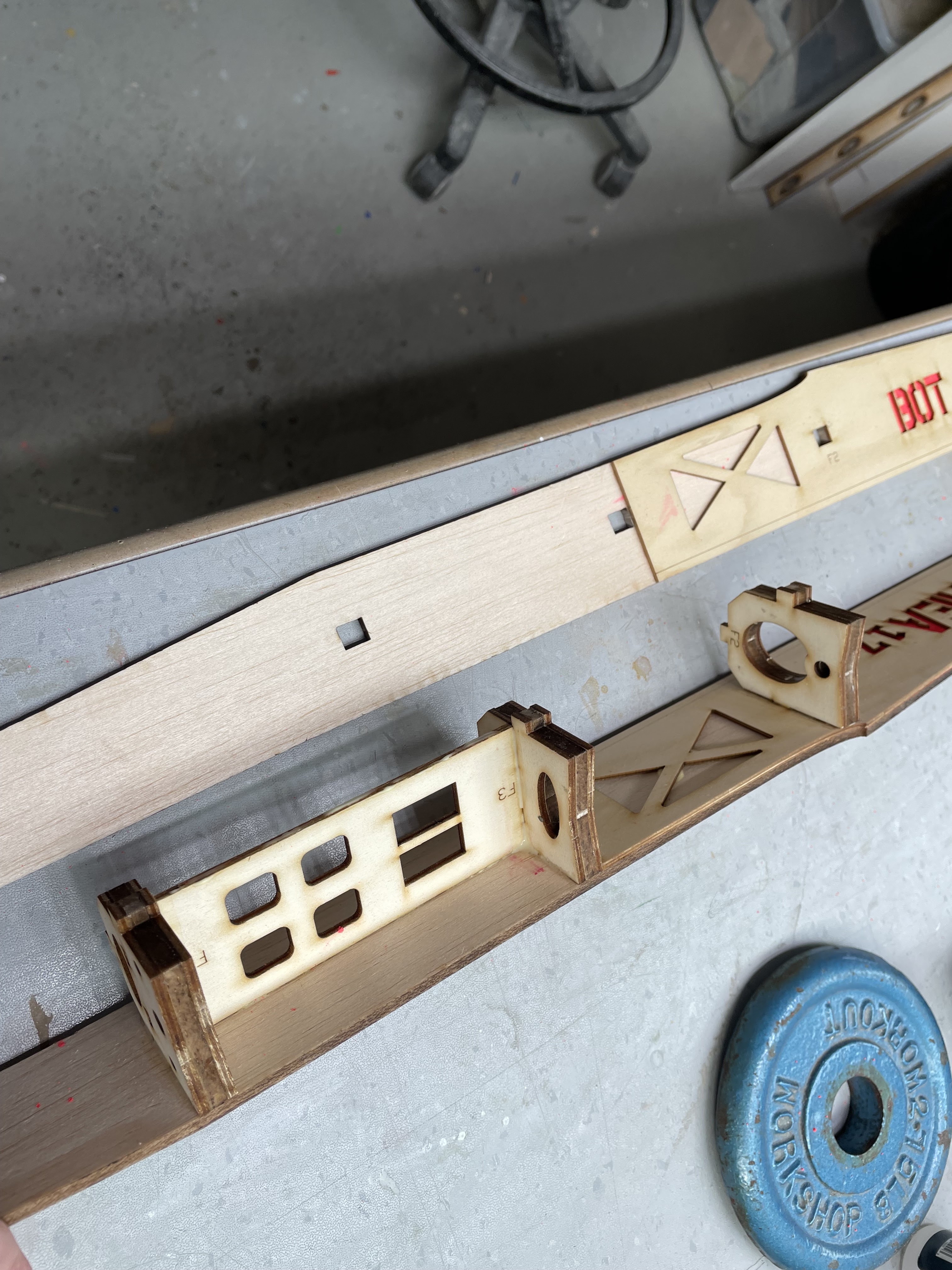
  1.  Glue the 1.5mm ply front doublers in place. F1 to F3
  2.  Glue the formers F2, F3 and F4 in place on the side pieces, do not forget to glue the servo tray between F3 and F4. 
  3. Slip the 6mm quad in from F1 to F3 and glue to the quads to laser marks F1 and F3
  4. We now glue clamp the sides and bottom pieces between F2 and F4. Leave the ends open at this stage it helps ensure no twists are introduced.
  5. You can now glue the rears quads ie F4 and through F5 to about 170mm from the end.
  6. Glue the bottom rear section to the quads and sides.
  7. Glue F1 formers and glue the bottom front to the sides and quads


Leave the top back section open at this stage.


Note the rudder servo goes on the same side of the rear slot  Typically on the left. The rudder tube needs to track straight down the lefthand side, do not cross over. The elevator tube starts in the righthand and crosses over to the middle at F5.


take time ensure the Fin pivot tube is straight.


Building the tail plane:
  • The tailplane is built bottom down flat on the bench.
  • Glue the front leading edge and main spar onto the bottom sheet.
  • Glue the ribs in place
  • Glue the joiner tubes in place.
  • Glue the 3mm ply end rib in place
  • Sand the top formers to produce a tapering trailing edge.
  • Glue the top cover in place


Making the Rudder:

The rudder is simple, just glue the parts in place on a flat board. You can if like carefully sand a tapering trailing edge.


The fin assembly:

The bell crank needs to be joined to the vertical part... we use a brass servo screw retainer. The shot is to use a centre punch with just enough pressure to close the back, and not enough to bind the joint.


We use a servo brass eyelet to join the bell crank to the connecting rod.
Use a centre punch to roll the edge over making sure you end up with a firm but moveable fit.

Make sure the servo drive clevis/Z bend is a neat fit. ie not loose.  

Build Photos


Wing Planform

Note, If you are looking for better handling in smaller thermals put a 1 to 2 deg bend in the 3/16 centre joiner piano wire to give more dihedral in the centre panels...


Airbrake set up using a metal strip and magnetic.


These trailing edge jigs are available on request from AREA17, otherwise have a look at the original BOT plans on how to scafe join the trailing edge.


Comments

Popular posts from this blog

Foamboard Spitfire Build

AREA17 Foam-board Spitfire (Night Flyer Addition) Based on The FliteTest Spitfire   https://www.flitetest.com/articles/ft-spitfire-build Find us on Facebook    AREA17 CoG on Wing Spar line (65mm from leading edge) Tools Required * Sharp Blade               * Clear tape * Ball Point Pen            * Optional 10mm x 0.5mm carbon blade * Hot Glue Gun            * Icy pole sticks * Set Square Hardware Required to Finish * Motor Brushless 2826 to a 2836 around 1300/1500kv 8x6 prop (looking for 180-220 watts) * 1500-2200 mah 3s lipo min 40c Not suitable for 4s..... * 30-40 amp ESC * 3 Mini servos 1.6kg to about 2.6kg or 4 with an optional rudder eg HXT900/ EMAX ES08A * 4 Extension leads * TX and min 4 Ch RX * Velcro for battery * Control linkages and horns * Paper ribbon attached to fin for combat ** Optional carbon blade spar reinforcement (10mm x 0.5mm) Parts Supplied * Three  Laser-Cut Foam Board Sheets     (Depending on supply can be the brown or white Flite Test foam b
  Combat Monkey Build Wingspan 750mm Laser cut 5mm Foam Board $15   The kit includes: Foamboard airframe components Ply and popsicle sticks for the motor mount. Corflute fuselage underside   What you need to complete: 3 x 9g Mini Servos  HXT900, MG90 etc Motor 2830 1200 kv to 2836 1500 kv 8x6 Prop (folding is better) 1300mah 3 cell lipo 30 amp ESC with BEC Sticky tape for hinges 3 control horns and 1.6mm piano wire 4ch RX Paper Party Streamers  about 40mm wide and at least 5m long   Tools: Hot Glue Gun and Sticks Box Cutter Scrape pieces of foam board to wipe off excess glue. Z bender Build With a sharp blade release all the foam board components from the backing sheet. Carefully deepen the hinge lines on the ailerons and elevator without cutting right through then bend back to form a hinge.  If you cut through, just tape the component back in place with clear sticky tape. Bevel the rearward side of the hinge surfaces forty-five degrees
  The full size  SZD-30 Pirat  is a single-seat multipurpose  glider aircraft  from the  Polish  firm  PZL Bielsko  which first flew in 1966, and started production in 1967. This RC scale version of the SZD-30 Pirat is 3.2 metre wingspan or 21% scale. Wing area:  62sq/dm, 960 sq ins Weight: 2.6/3kg CoG: 76 to 80mm from leading edge Servos: 2x Aileron min 5kg, 1x Elevator min 2.2kg, 1x Rudder 4kg, 2x Airbrake 2.2 kg, Tow Release 4kg (based on deflection at 70kph)  This kit  includes: *Fuselage – CNC Foam cores ready for 2mm balsa planking. $50 *Wings –Built up, kit includes ribs, leading and trailing edges, main spars and shear webs. $60  or EPS foam version cores, jackets and end ribs $50 *Tailplane – EPS foam core ready to be laminated with 1.0mm balsa – $10  *Fin – EPS foam core ready to be laminated with 1.5mm balsa $10 *3d Printed canopy frame $10 *PVC Clear Canopy $10 *12mmx10mm Ali Joiner Bar $5 This kit does not contain electric/electronic components, balsa planking, wing skins,